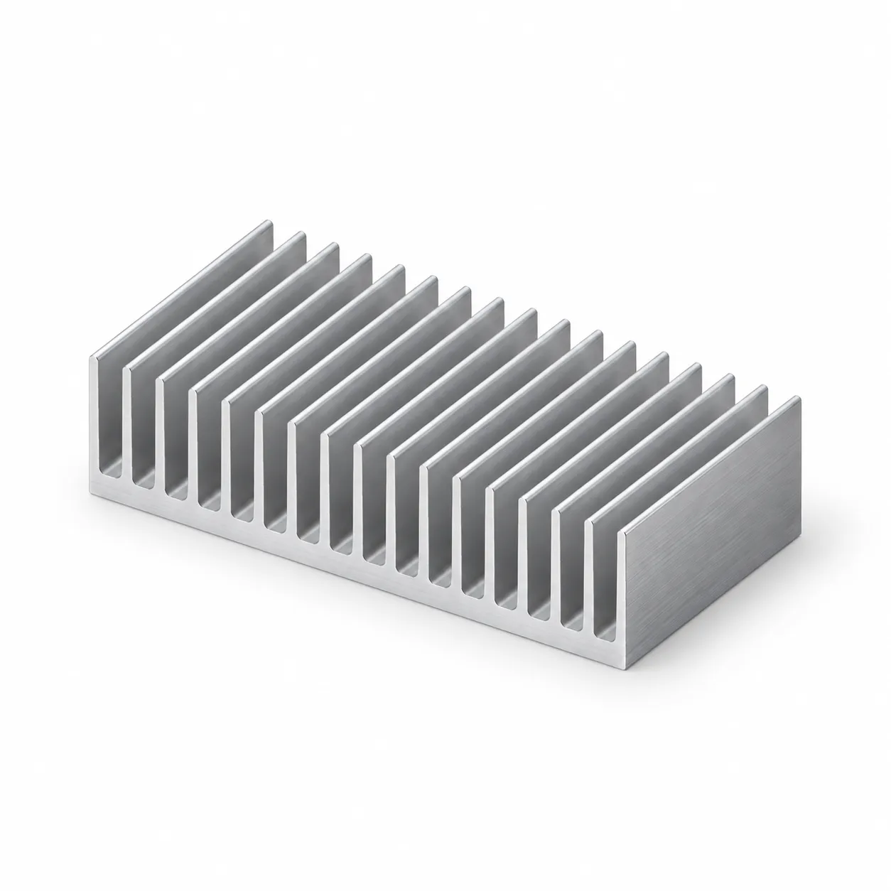
100 AS Aluminum Heat Sink: Thermal Solution and Selection Guide
Review the 100 × 25 mm 100 AS heat sink profile, mounting requirements and thermal evaluation steps.
100 AS: a 100 × 25 mm aluminum heat sink
100 AS is a finned aluminum profile used to evaluate a heat path from electronic components to the surroundings. The current catalog specifies a width of 100 mm, an overall height of 25 mm, a fin height of 21 mm and a base thickness of 4 mm. The material is 6063-T5 aluminum.
Evaluate the cross-section and thermal performance together
The 100 mm width is an initial mechanical criterion for the mounting surface. Profile length, component position on the base, contact area and fin orientation relative to airflow also matter. Fins increase the surface exposed to air, but the cross-section dimensions alone do not determine the allowable heat load.
How should a thermal resistance curve be read?
A value in K/W is meaningful only with its measurement points and test conditions. An old graph should not be used to predict application performance without the profile length, air velocity, orientation and temperature difference. Use the current cross-section drawing, request the relevant thermal data or test a sample under actual operating conditions.
What information is needed for your project?
- Power loss transferred to the heat sink and maximum ambient temperature.
- Cut length, quantity and available mounting volume.
- Hole pattern, contact surface, thermal interface and insulation requirements.
- Natural or forced airflow and target component temperature.
Cutting and machining options
Drilling, tapping, milling and surface treatments are evaluated against your technical drawing. Follow the link below for the current product and its technical PDF drawing.